 |
| OpenSCAD |
 |
| First try |
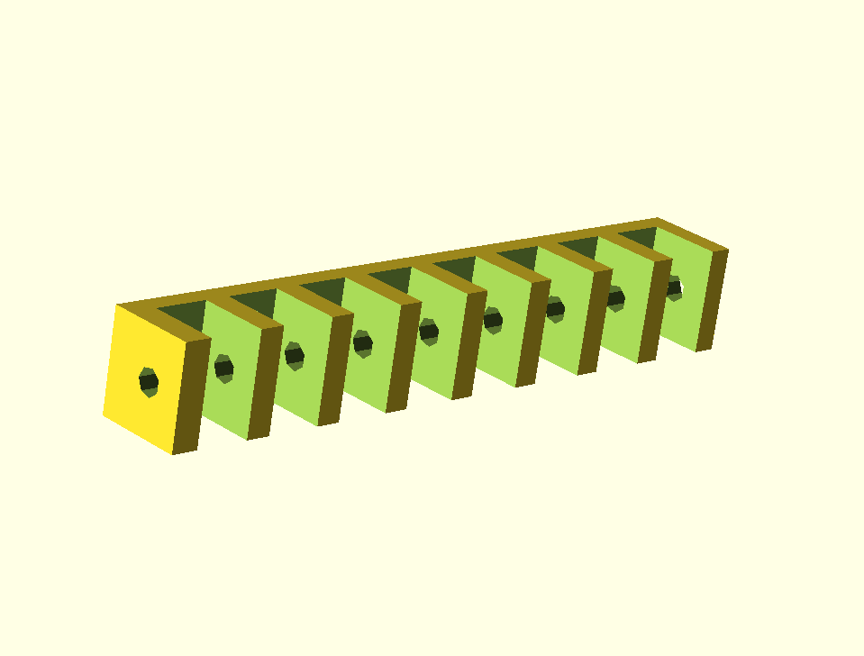
The code to create the image above:
module PencilHinge()
{
  hole_width = 8.1;
  hole_count = 8;
  total_width = 98;
  projection_count = 9;
  projection_width = (total_width-(hole_count*hole_width)) / projection_count;

  difference()
  {
    union()
    {
      cube([98, 15, 14], center = true);
    }
    union()
    {
      for ( i = [0:7] )
      {
        translate(v=[i *(hole_width+projection_width)-(total_width/2)+hole_width,0,4])
        {
          cube([8.1, 16, 16], center = true);
        }
      }
      translate(v=[0, 0, 1])
      {
        rotate(a = [0, 90, 0])
        {
          cylinder(h = 100, r=1, center = true);
        }
      }
    }
  }
}

PencilHinge();
After playing one hour with it I came up with the design above. When you look at the full size image you can see that the holes are not round, but consist of just seven flat surfaces.
 |
| Second iteration |
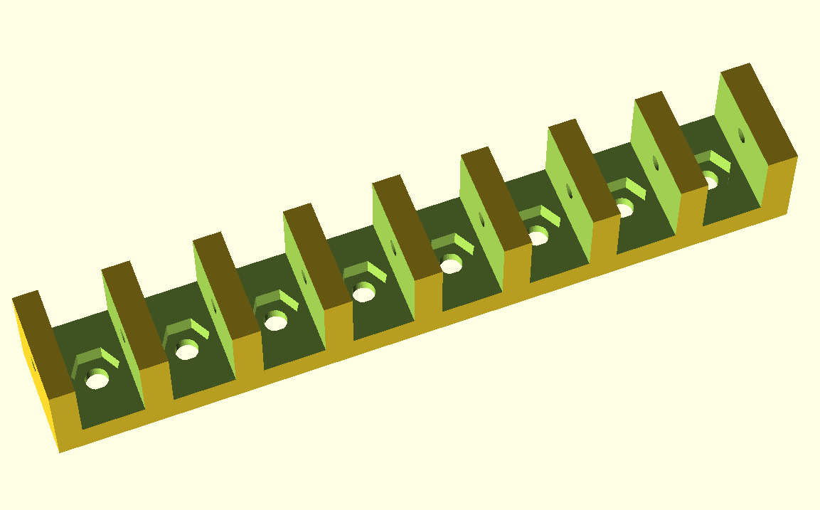
A second night working on it I found out that you can set the number of surfaces used to make the cylinder holes: I had to add $fn=36 to the creating of the cylinder. Where 36 is the number of surfaces: cylinder(h = 100, r=2, center = true, $fn=36); I added eight holes in the bottom plate to be able to mount it to the robot frame. The holes for the nuts were, easy now that I now how to set the number of surfaces of the cylinder. I just needed six surfaces for that.
The code for the image above:
module PencilHinge()
{
  // Sizes in mm
  round_r = 3;
  pad = 0.1;
  mounting_hole_radius = 1.5;
  mounting_nut_r = 6.3 / 2;
  mounting_nut_h = 2.5;
  mounting_nut_facets = 6;
  hole_count = 8;
  projection_count = hole_count + 1;
  hole_width = 8.1;
  box_l = 98;
  box_w =15;
  box_h = 14;
  projection_width = (box_l-(hole_count*hole_width)) / projection_count;

  difference()
  {
    union()
    {
      // The main part
      cube([box_l, box_w, box_h], center = true);
    }
    union()
    {
      for (i = [0:7])
      {
        translate(v=[i *(hole_width+projection_width)-(box_l/2)+hole_width,0,4])
        {
          // Holes to hold the pencils
          cube([hole_width, box_w+pad, box_h], center = true);
          // Mounting hole
          cylinder(h = box_l, r=mounting_hole_radius, center = true, $fn=36);
          // Nut hole
          cylinder(h = (mounting_nut_h*2)+box_h, r=mounting_nut_r, center = true, $fn=mounting_nut_facets);
        }
      }
      // The axle
      translate(v=[0, 0, 3])
      {
        rotate(a = [0, 90, 0])
        {
          cylinder(h = box_l+pad, r=1, center = true, $fn=36);
        }
      }
    }
  }
}

PencilHinge();
 |
| Final design |
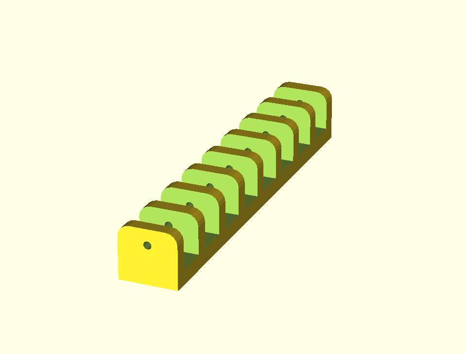
It took a third night to come to the final design shown in the image above, with nice rounded corners. I used the cube fillet module for that. I only had the replace cube([box_l, box_w, box_h], center = true); by cube_fillet([box_l, box_w, box_h], vertical=[0,0,0,0], top=[round_r,0,round_r,0], center=true); Note that the cube filet code to get the rounded corners is bigger in size than the pencil hinge code.
No comments:
Post a Comment